|
|
Ground Hawg Towable Backhoe |
|
|
|
Ground Hawg Towable Backhoe |
|
Build your own backhoe! (Part 2)
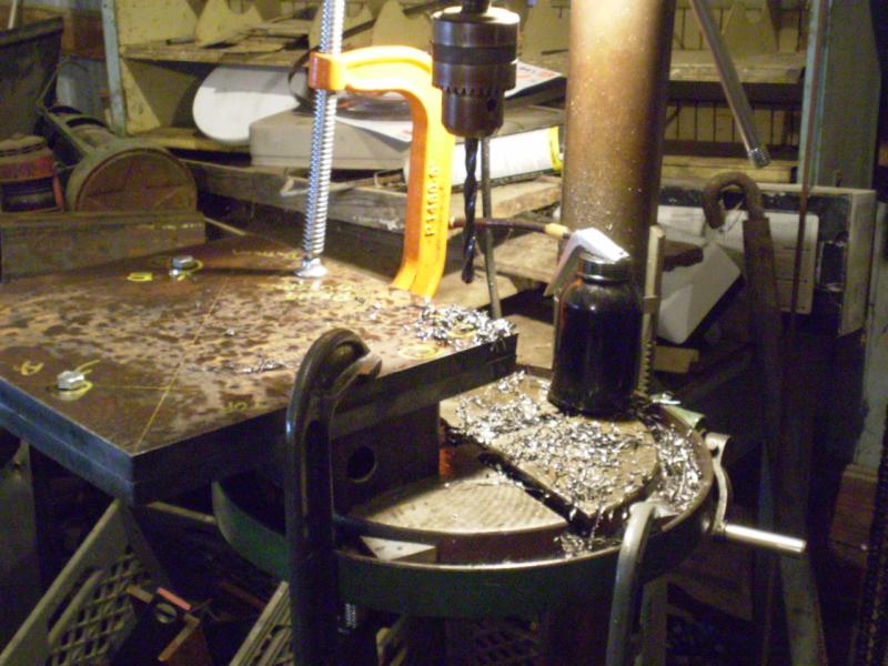 | 3 August 2007 Drilling the holes in the main dipper arm plates. There were three one-inch holes to drill. The plates were clamped together and the holes first drilled to 3/8". Bolts were slipped through as each hole was drilled.
These plates were HEAVY. Each of the plates shown weighed about 25 pounds, so the two together weighed over 50 pounds. Trying to wrestle that around while lining up the drill press was a bit of a trick. If you have a mill, that would be the way to go with certain holes like this. For another project of this magnitude, I would get one of those milling vises for a drill press. While it wouldn't be big enough for pieces like this, there were other pieces that it would have been handy for. As it was, I did a lot of unclamping, repositioning, and reclamping. But I can't imagine attempting this project without the drill press. |
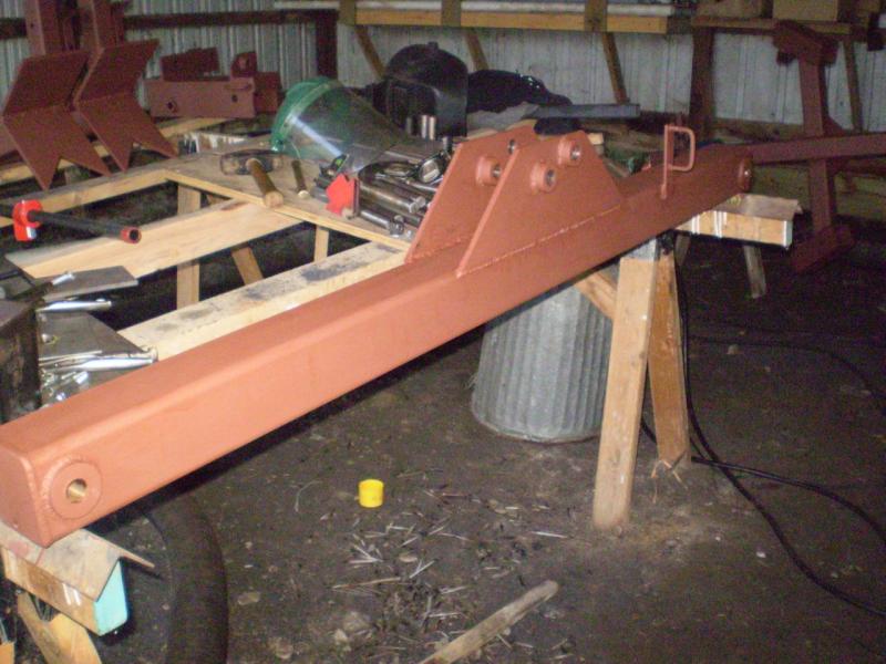
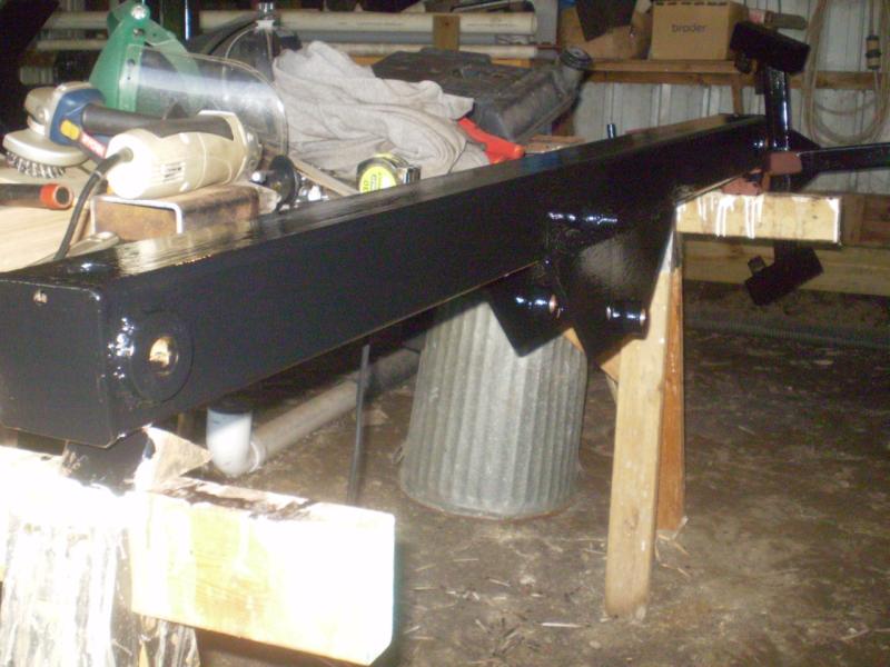
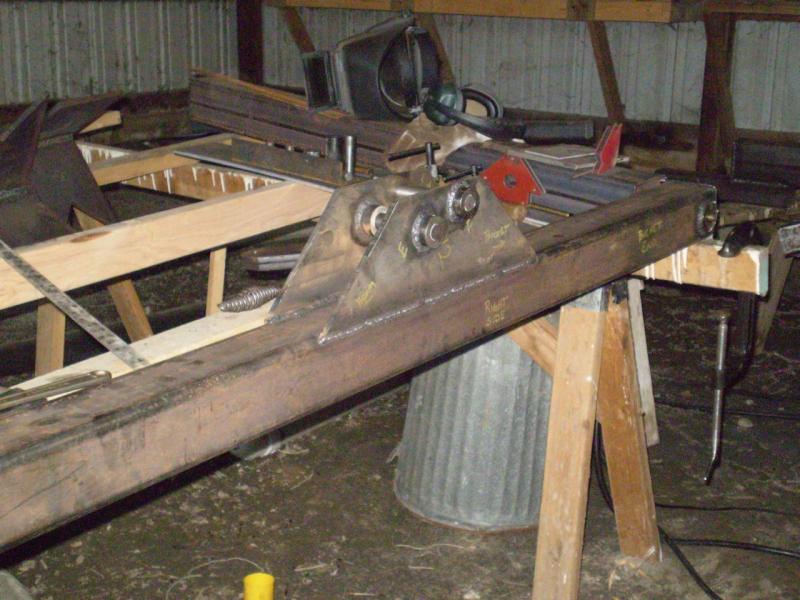 | The boom has been completed. |
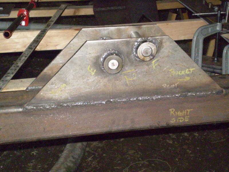 | A close-up of the boom bracket. Again, note my markings to keep things in perspective. |
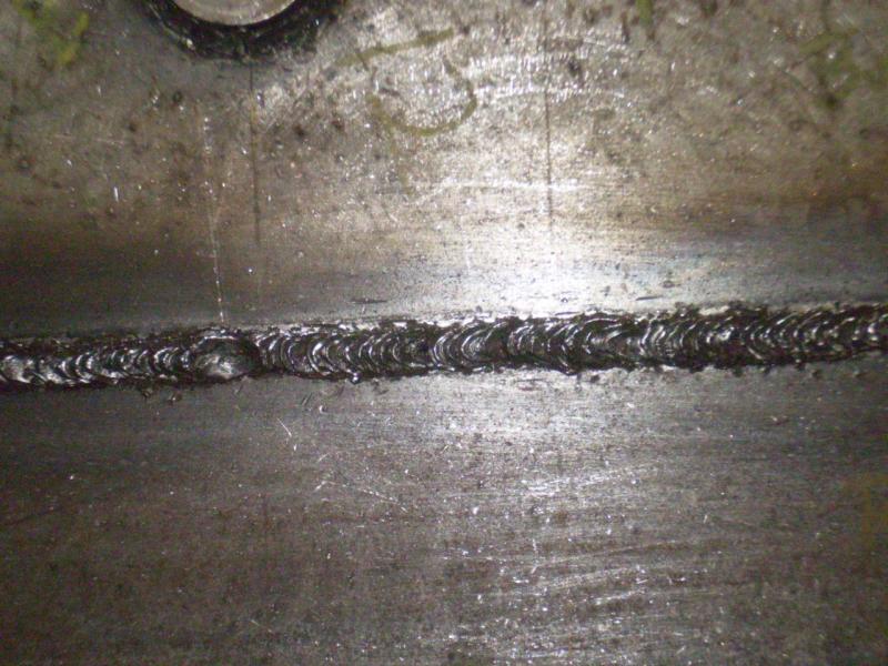 | A close-up of the boom bracket weld. |
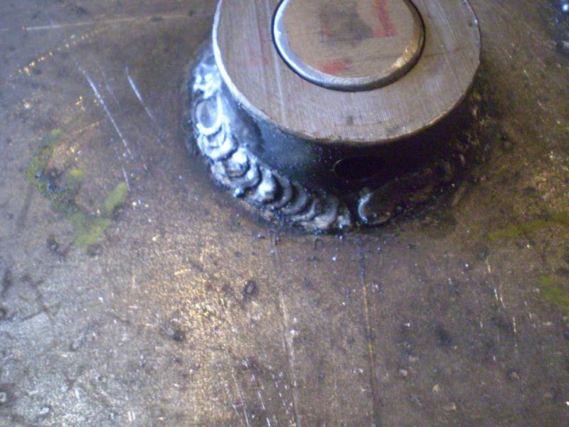 | A close-up of one of the bushing welds.
I had read that when using 6011 rod, ideally you should use the "whip" method, where you hold the rod in one place for a short period of time, then "whip" it forward and back, allowing the puddle to freeze a bit and not coming back as far as you were. When done right (it was stated), it should look like a series of overlapping dimes. Overall I didn't think my welds came out too bad, for an amateur. |
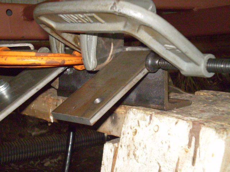
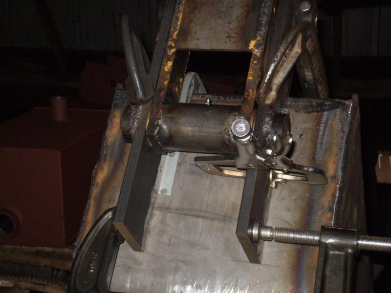
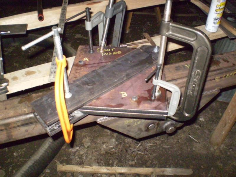 | Clamping up for the welding the dipper arm reinforcements. |
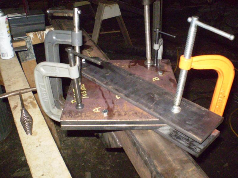 | More clamping. These are going to get a LOT of heat, and we are trying to keep them from warping.
As it was, I did have some distortion. I ended up running beads along the opposite side (and grinding this down) to distort things back in the other direction. I was quite satisfied with the results. |
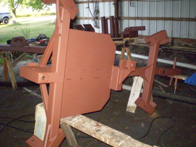
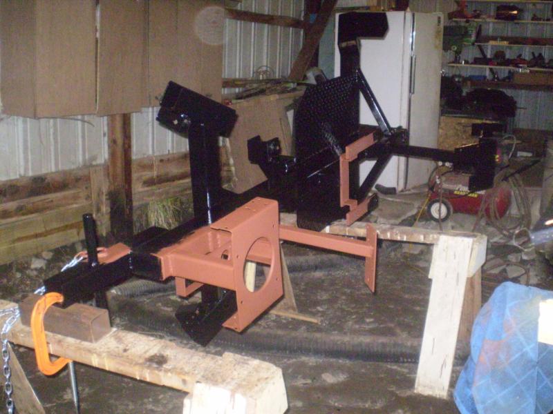
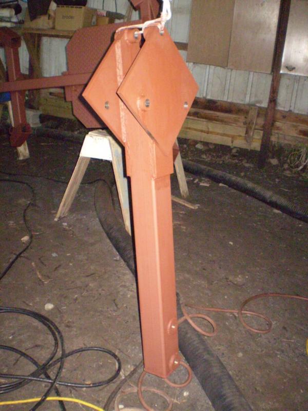 | 11 August 2007 Michigan's summer humidity has come along, so it's time to get some of this raw steel primed. Here the dipper arm is hanging from a rope tied to one of the trusses. |
 | The primed boom with attached hose bracket. |
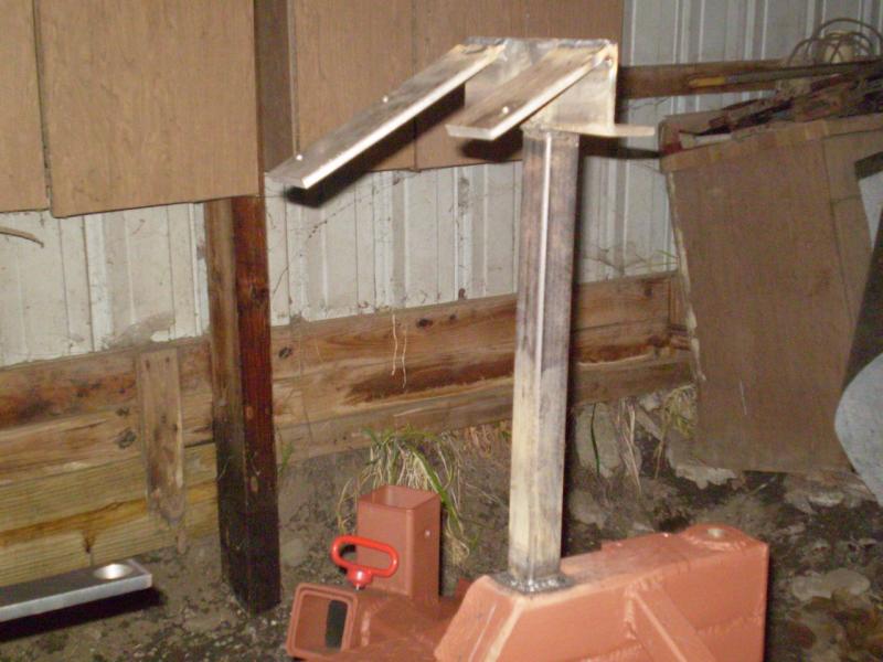
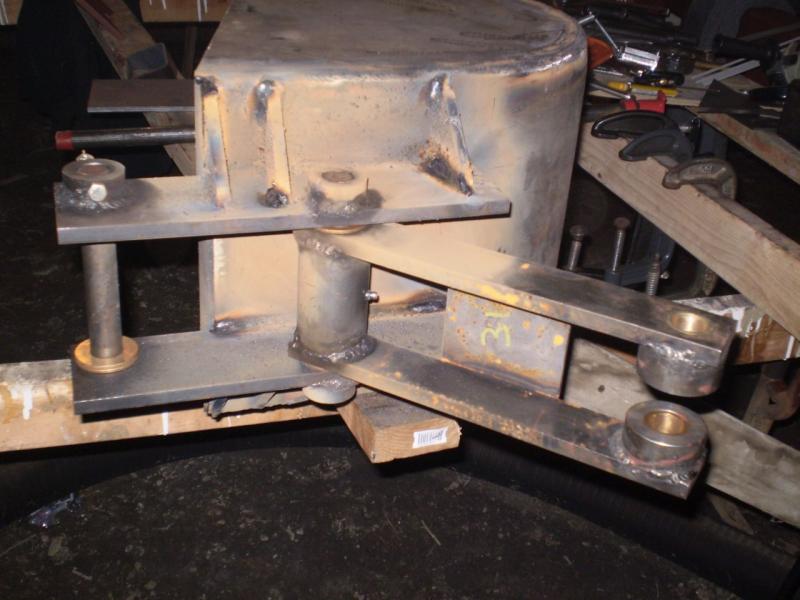
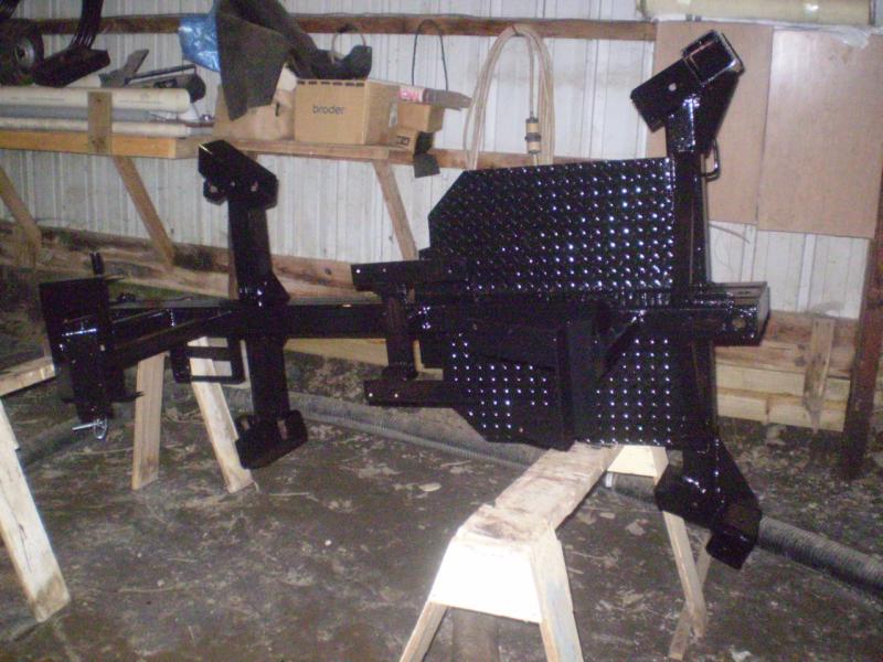
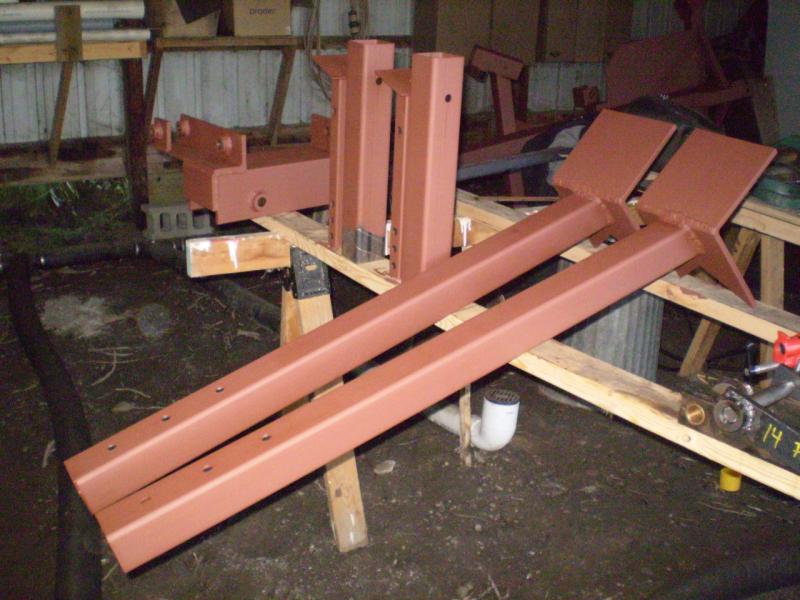 | Stabilizer arms, axle tubes, rear legs, and boom pivot. |
 | Another view. I'm being watched by Duke. |
 | The main frame. This thing is looking pretty sharp now that all the heat discoloration is being covered up with the primer. |
 | The bottom of the frame. |
 | The rear swing piston bracket and rear axle. |
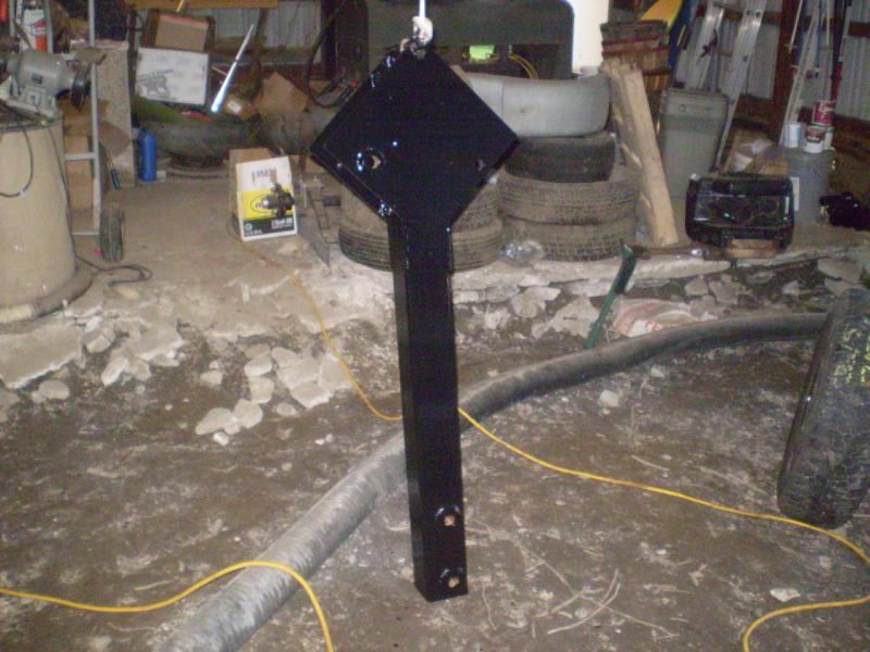
 | 18 August 2007 Time for the seat bracket. This will be adapted from the l&g tractor.
The big holes in the front do not have any purpose. These two pieces started out being bucket links. I needed a 1-1/4" hole in the end and tried to do it on the cheap with a hole saw. But the holes were too loose to hold the bushings that would need to go through them. I had to break down and buy a 1-1/4" drill bit. These pieces became scrap. However, now I could use them here. The main bracket was built on the bench. Now I'm clamping it up for welding to the frame. Note the red-handled pin is holding one of the axle tubes in place. |
 | First it will be tacked on this side. |
 | There is just enough room for getting a rod in there and tacking it on the other side. Once tacked, the clamps and angle iron will be removed and I will full-weld around the base. |
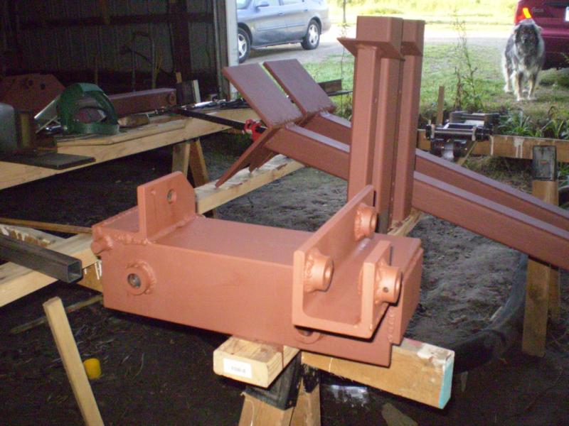
 | And once welded in place, it's not going anywhere. |
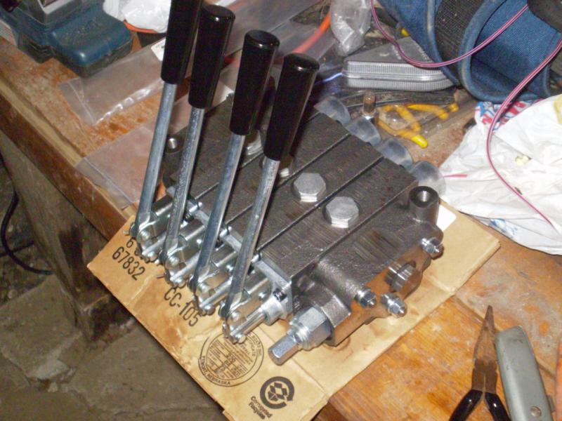 | The hydraulic stack valve.
This is something else I needed to learn about. For those who are not familiar with the concept, this was actually a purchase of seven components an input section, an output section, four work sections, and a properly sized set of tie rods to bolt the whole thing together. You don't necessarily buy a valve that fits your application. Instead, you buy pieces that "stack" together to get the desired valve configuration. I spent several hours on-line looking for 4-spool valves that would work before I started to understand this concept. |
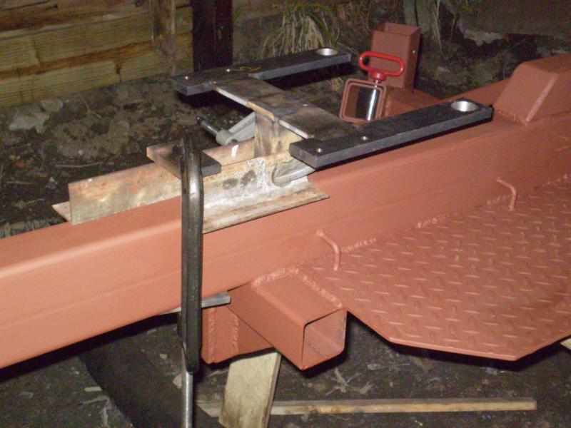
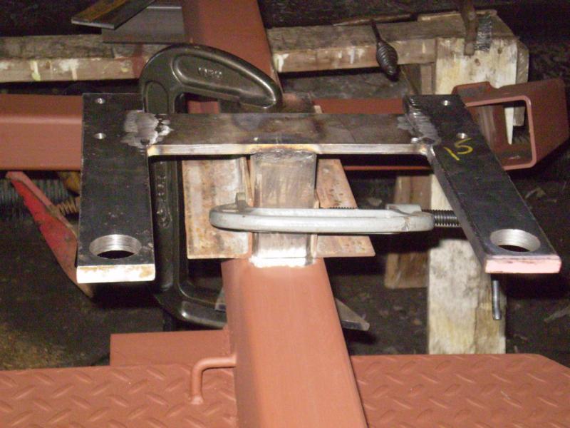
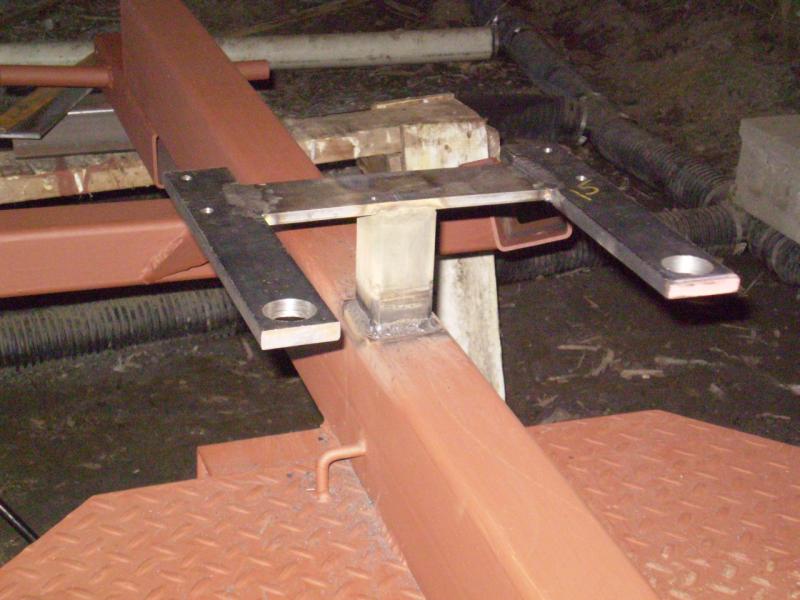
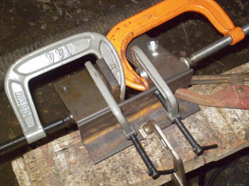 | Clamping up the hydraulic valve bracket. This was tricky because of the angles involved, and the fact that the two flat plats weren't exactly parallel when bolted to the hydraulic valve. So I first had to clamp a couple of small scrap pieces in place (using the small clamps), then clamp the angled plates against the small scarps (using the big clamps). Finally configured it the way I wanted it, but it took awhile. Here it is clamped to the (admittedly wooden) sawhorse just prior to welding. |
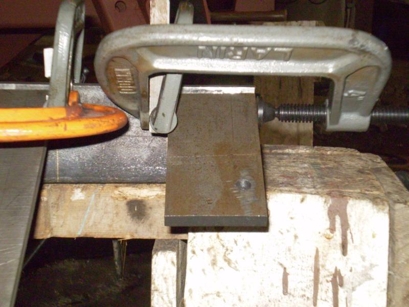 | Another view. |
 | Still another view. It was impossible to get one picture that could show everything needed if I ever do this again. |
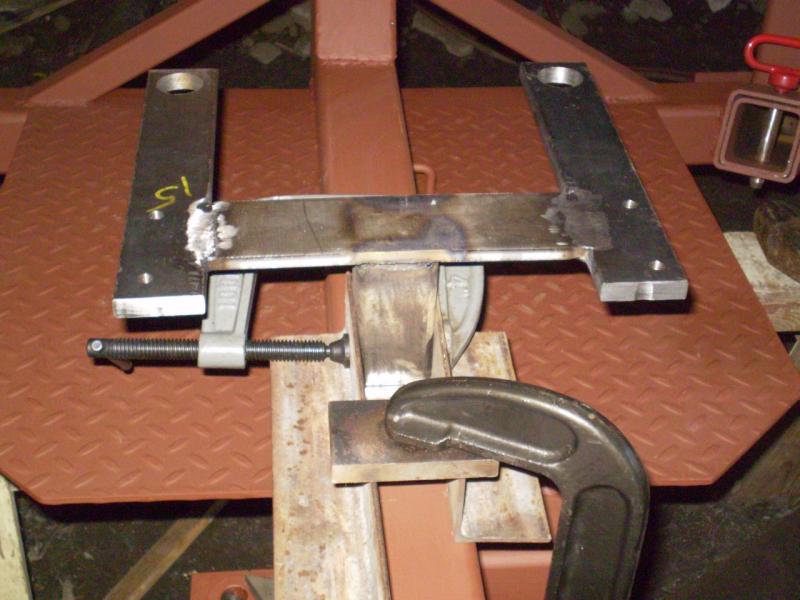
 | The angled pieces are welded in place, and the upright is positioned for welding. |
 | The hydraulic valve bracket completed and welded in place. Yes, I did clean the primer off the metal before welding the upright to the frame! |
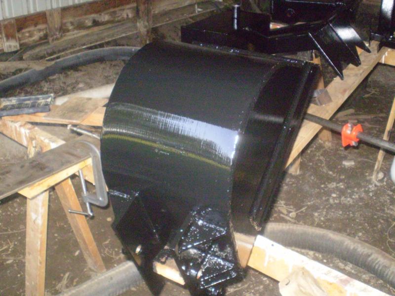
 | 20 August 2007 I did not take pictures while curling the bucket, and I probably should have. But here is some explanation.
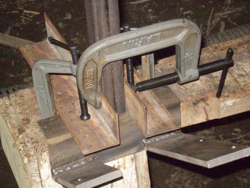
The bucket and sides are made of 1/4-inch steel. Templates for the sides came with the plans, and my steel supplier simply cut them to match. To create the initial curl, I purchased a 10,000 lb. rated load binder strap at a discount tool house ($12.99) that had the flat hooks on the ends. I laid a 12-inch firewood log in the middle of the plate, hooked the load binder to each end, and started cranking it down. I did take some care as to where arms, legs, fingers, etc. were in case something gave. Actually the most difficult part was getting the initial bend started. Once the plate started to "give" and curl, it went more easily. Once the initial curl was complete I started tacking in the sides. I tried using a pipe clamp to bring things in as suggested by the author of the plans, but didn't really have much success for the amount of effort expended. I ended up going back to the load binder. In the end, it fit up pretty well. I had a 1/4 inch gap at the middle of the curl, and I simply sledge-hammered that closed. Then I ran a full bead all the way around, both outside and inside. Used the grinder to smooth it off a bit, and voila! Most people who have seen this, including my mechanic friends, are amazed that this is a fabricated bucket. This picture shows clamping up the brackets in preparation for welding them to the back of the bucket. |
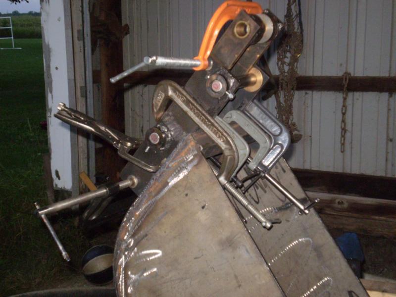
 | The little (due to limited clearance) pieces of aluminum angle were clamped along some pre-drawn lines to keep things square. The bracket fit around these and was then clamped against the bucket. The bottom C-clamp is keeping a couple of things square within the bracket itself. |
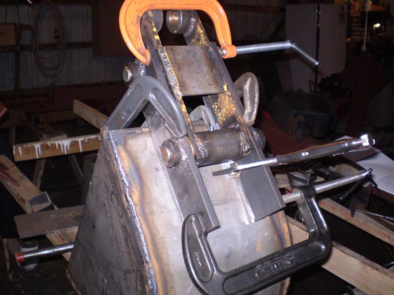 | The orange clamp at the top is also helping with keeping things square. |
 | 21 August 2007 And here it's complete. The brackets have been welded on, and the supporting gussets have also been added. |
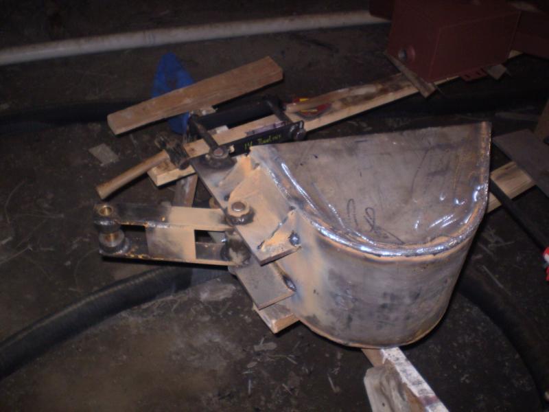 | One other view showing the entire bucket. While it doesn't appear very large in this picture, the top edge is 22 inches long, and the bucket is 12 inches wide. |
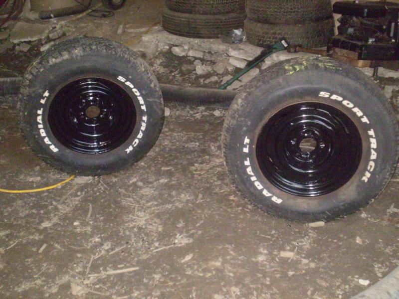 | 2 September 2007 Now we are getting into final painting! Here are my junkyard tires and wheels, ready to mount. How many backhoes have you seen with white-lettered tires?
Something to consider. This is a towable backhoe, so I wanted road-worthy tires. Also, because this will be used in who knows what kind of terrain, I wanted larger tires so I wouldn't get caught in small ruts or holes. These are 15-inch 5-bolt wheels with truck tires on them. (The 5-bolt hubs were only $1 each more than the 4-bolt hubs at NorthernTool.com, so I opted for the 5-bolt.) |
 | The 16-HP Briggs Twin has been removed from the donor tractor. The motor mount and pump bracket still need to be fit to it. |
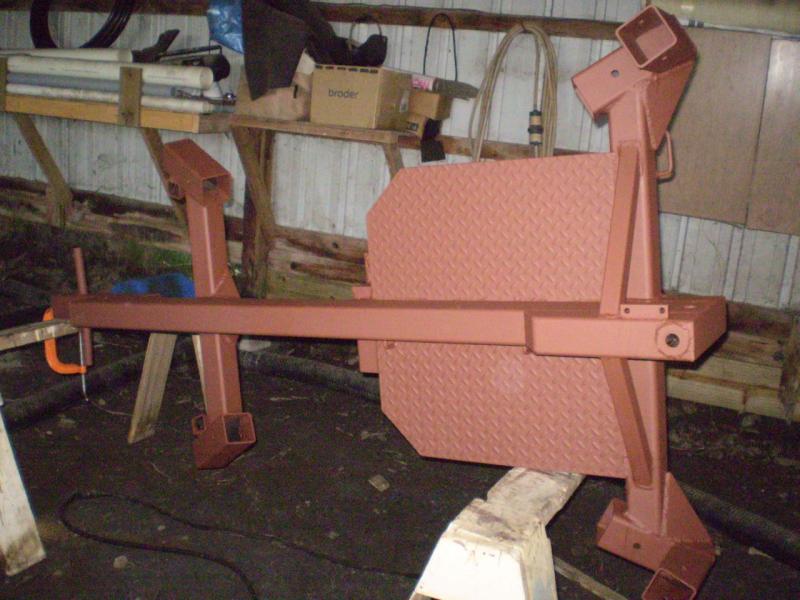
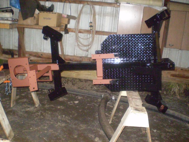 | Final painting is progressing. The seat bracket had to be slightly modified (to allow for clearance for the "well" in the bottom of the fuel tank, and the motor mount, dash board, and battery bracket have been added. The top part of the motor mount is the section of frame from the donor tractor where the motor had been previously mounted. (No worries about whether the holes are in the right place!). The uprights are a piece of left-over 3x3 tube steel cut in half (home-made C-channel). The pump bracket is then a piece of flat stock with the holes drilled out, then welded in place in the uprights. The dash board will have the key switch, light switch, starter solenoid, choke and throttle controls. |
 | Here is another view. Safety chains and related welded links have also been added. |
 | Final paint on the boom pivot... |
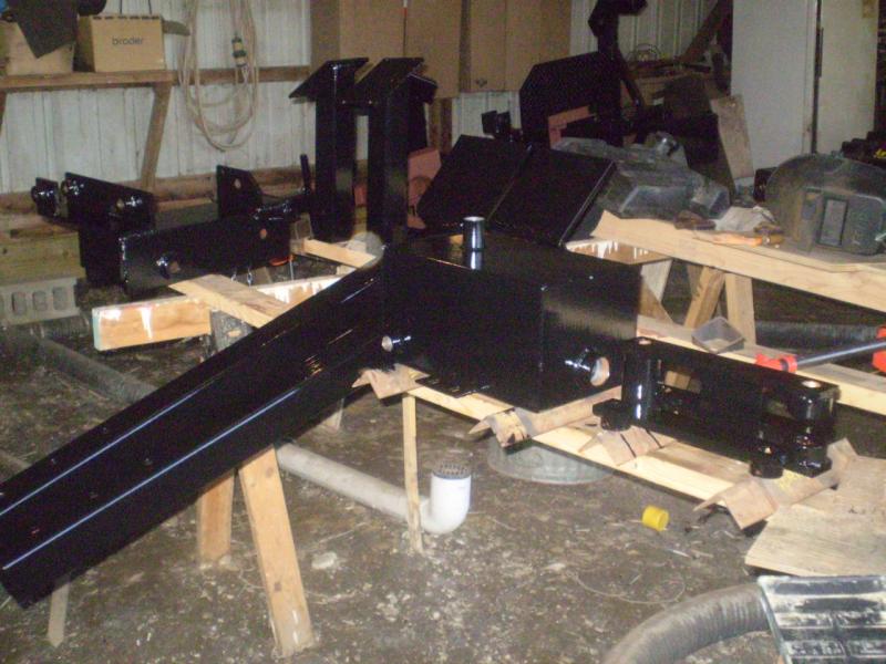 | ...and most of the other parts.
A word about color. Of course, color is a very personal thing, and how you paint your home-built piece of equipment is up to you. We discussed color as a family and decided together what color to use. I haven't seen a black backhoe before, but once it was suggested, I liked the idea. With the red-handled pins and red cylinders, I'm very happy with the final result. Of course, one limiting factor was that the color would have to be available in Rustoleum Enamel. Fortunately, black was not a problem. Of consideration, however, is the fact that if this is being towed down the road, black will not be as visible as other colors. When I purchased the paint, I saw that Rustoleum also has a very nice Safety Red and Safety Yellow. Had we not already settled on black, I may have gone with the yellow. (And nothing says I can't repaint in awhile, either.) |
 | Here is a nice, shiny, never-used bucket. Note the reinforcements on the sides. These are plow parts purchased at the local farm store. These are hardened, as the two band-saw blades can attest to that were used to cut the angle at the front end. Of course, the welding heat would affect that some. |
 | The boom is ready to go... |
 | ...and so is the dipper. |
 | Final paint is on!! |
 | At this point, here is what is left of the donor tractor. The front axle is in the parts bin awaiting some future project, and the steering mechanism will go there as well. The rear wheels will also be saved, while the transmission and vari-speed pulley may get auctioned. |
|
|
|