|
|
Ground Hawg Towable Backhoe |
|
|
|
Ground Hawg Towable Backhoe |
|
Build your own backhoe! (Part 1)
| This website is documentation of my project, building my own backhoe. This is something I've been wanting to do for a few years, but didn't have the right opportunity. Then I developed a problem in my yard that was not going to be solved with a shovel and arm muscles. My wife, sensing my frustration, asked what she could do. "Get me an excavator!" I yelled. Thus began my project.
I had previously determined that I liked the backhoe plans from UBuildItPlans.com, though the CADDigger from CADPlans was a close second. So I obtained plans in late April 2007 and started preparing. This project would be built in my garage. My garage is a 26'x40' pole barn. It has a broken cement floor on one end (remnants of a previous carriage barn) and a dirt floor on the other end. Better yet, the dirt part was dug out (by hand) a couple of summers ago in preparation for good backfill and a new cement floor. Then a job change and lack of time prevented the completion of that project. (Maybe yet this fall....) So in the pictures you will see the dirt floor, drain tile, and messy shop. Such is life! In May, an old l&g tractor was purchased through e-bay for $135. The front tires wouldn't hold air and the mower deck was shot. But the 16HP Briggs Twin engine worked just fine, and the seat was in good shape. Being a vertical shaft engine instead of horizontal, I would have to make some adjustments. But I would have more available horsepower than specified, and electric start, to boot! I purchased steel to start making the required pins and bushings. I also purchased the kit available from UBuildItPlans.com that contained all the bronze bushings and the large bushing housings made from D.O.M. tube for $300. As far as I could tell, that price was only a little over the cost of material, and so seemed quite reasonable. Two other primary tools purchased through e-bay were a heavy-duty 3/4HP drill press ($78) and a 4x6 horizontal band saw ($100). I can't imagine taking on this project without these. 135-degree split-point drill bits, sized from tiny through 1-inch, and some other miscellaneous tools were also purchased. Now I'm really ready to get started! | |
 | First, a few pictures from around my shop, starting with this. After completing my welding class four years ago, I purchased this 1949 Lincoln pipeline welder. In fact, I picked up the welder, leads, extra leads, about 30 lbs. of rod, a trailer axle, trailer fenders, and trailer tires (plus spare), the wheeled cart on which it sits, welding helmet, chipping hammer, and gloves for $400. It runs great, uses little gas, and doesn't affect my electric bill. Once the cement floor is in, building the trailer will be one of the next projects. |
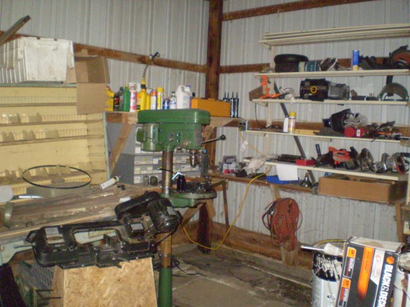 | The general work area of my shop. The drill press and band saw are in place. Actually, the band saw ended up turned 90-degrees to allow the necessary clearance. You can't see my main work bench, but that's okay. Neither can I. |
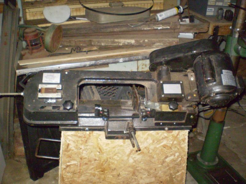 | A closer view of the band saw.
I lead an interesting double life. At heart I am a farmer / country boy. But by profession I am a computer professional with an excellent job in the city. Many of the people I work with find fascinating the things I like to do with my free time, as it is so foreign to what they do. Some of these pictures are intended to help the uninitiated understand various tools and how they work. |
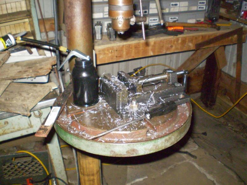 | A closer view of the drill press. As you can see, I've already been making chips, drilling holes in the ends of the pins. |
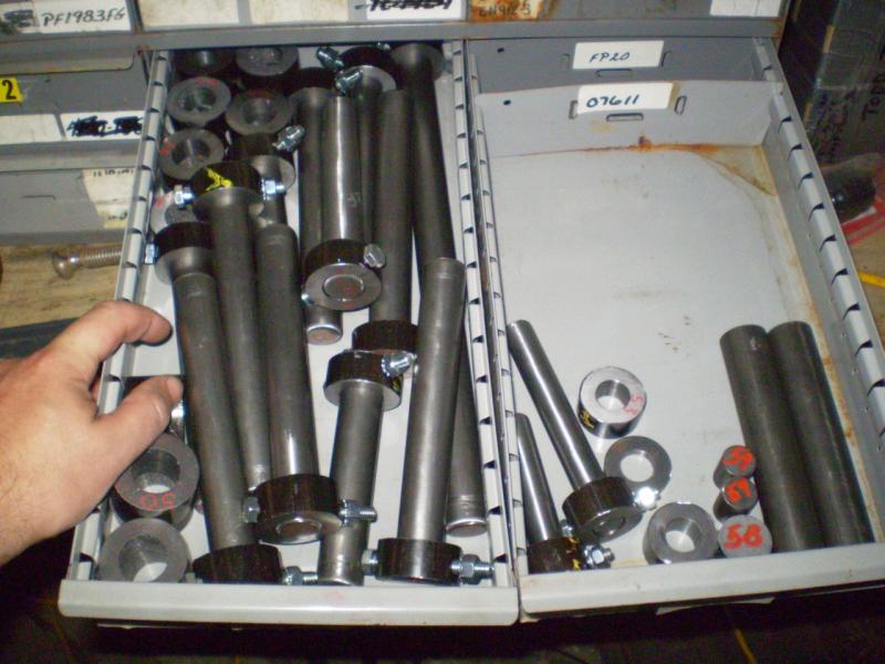 | 24 June 2007 The pins and bushings have been cut to length and drilled. |
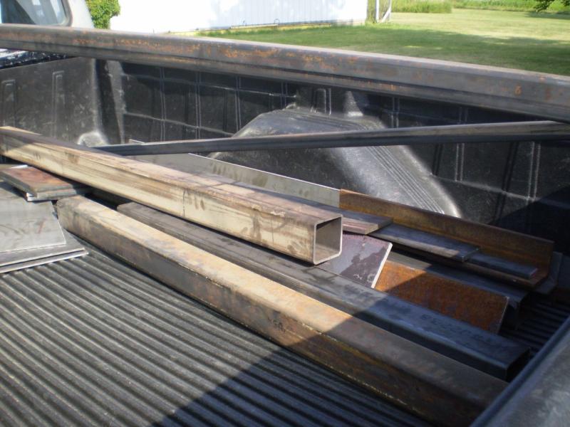 | 27 June 2007 $1000 of steel sure doesn't look like much. It's also hard to see how this could possibly add up to much of a backhoe. |
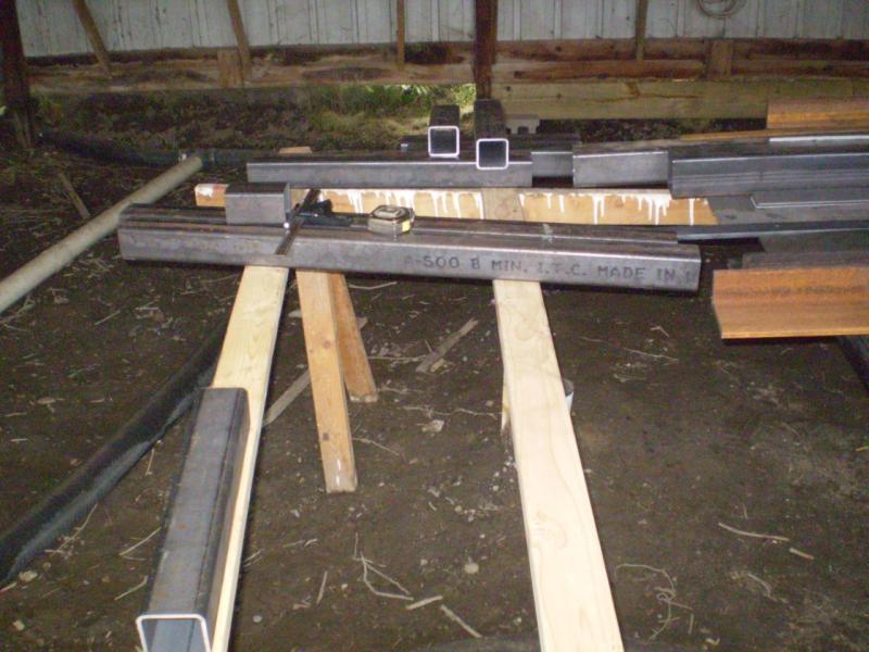
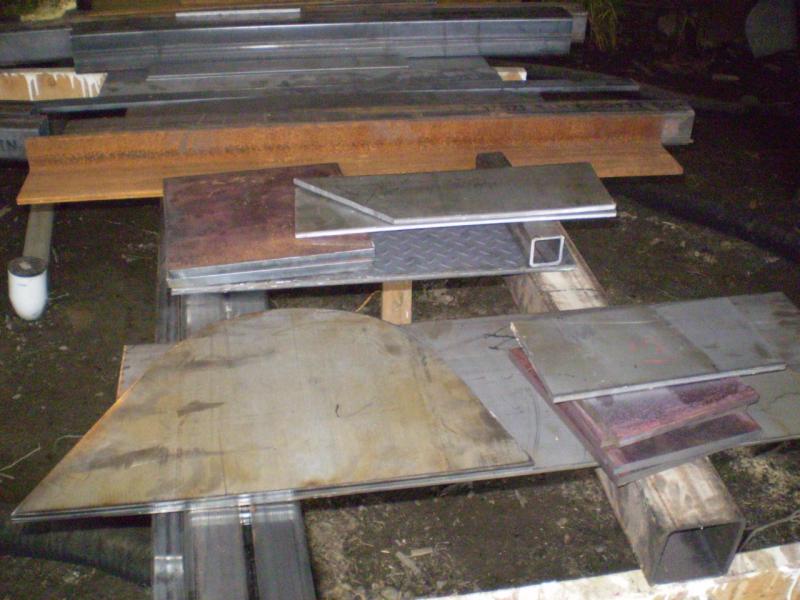
 | Unloaded into the garage it still doesn't look like much. Notice the pre-cut bucket sides towards the left front. The saw horses will receive additional reinforcement before the day is out. |
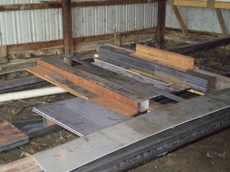 | Another view. It just doesn't look like much. |
 | Starting to cut steel. If you've never seen a horizontal band saw in action, this is typically what it looks like. |
 | And just a couple of minutes later and we're almost through the piece. |
 | By the end of the day several pieces have been cut to length. |
 | One of the boom brackets has also been started. |
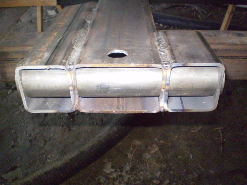 | 7 July 2007 Had an extra day in here to get more done! The front of the frame has had the holes cut with a hole saw, the pieces have been lined up, and the frame pieces welded. This is the main pivot bushing housing. It has yet to be welded in place.
Here is a little trick. When I was cutting the holes with the hole saw, as expected the hole saw became quite hot. And as it heated, it quit cutting as well. I took a block of ice about the size of my fist and held it against the hole saw while cutting. The cooling effect made the holes cut MUCH faster. |
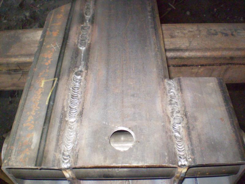 | Another view, showing the welds. 99% of the welds on this project used 6011 rod, electrode positive. I was very pleased with the penetration. I started using 1/8" rod at about 150 amps. Later I went to 5/32" rod at about 180 amps. I really liked the heavier rod. |
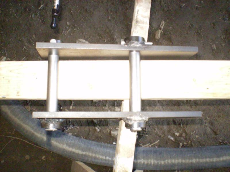
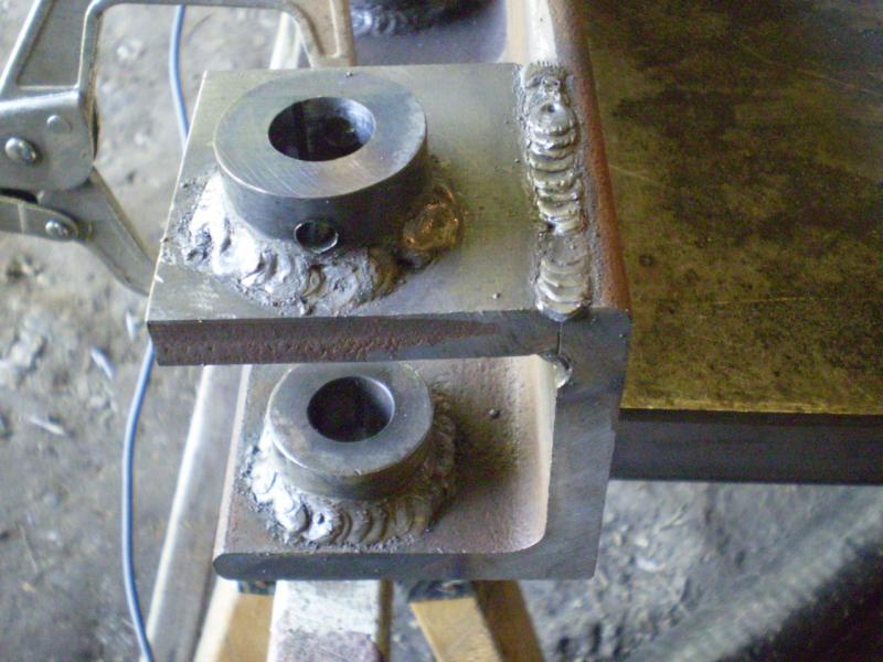
 | This will become the front connection point for the swing piston. The bushings have been welded in place, and the stub piece (top) is going to be welded to the angle. One pin through the bushings to keep things in line, and two spacers for proper distance. |
 | The bracket that will eventually be welded to the back of the bucket. |
 | The stabilizer legs and feet have been cut and welded. I did use a filler rod on these two corner welds after the first pass with 6011. |
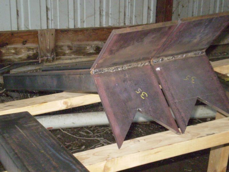 | Another view of the stabilizers. |
 | A close-up of the swing piston connecting point after welding. |
 | A close-up of the weld. As stated, I was quite pleased with the penetration of the rod. There was a slight bit of under-cutting, but what can you expect from an amateur welder? |
 | Another view showing more of the welds. |
 | The boom pivot after completion. All-in-all, quite a complicated (and HEAVY) piece. |
 | The pivot bushing housing is welded in place and the grease fitting added. |
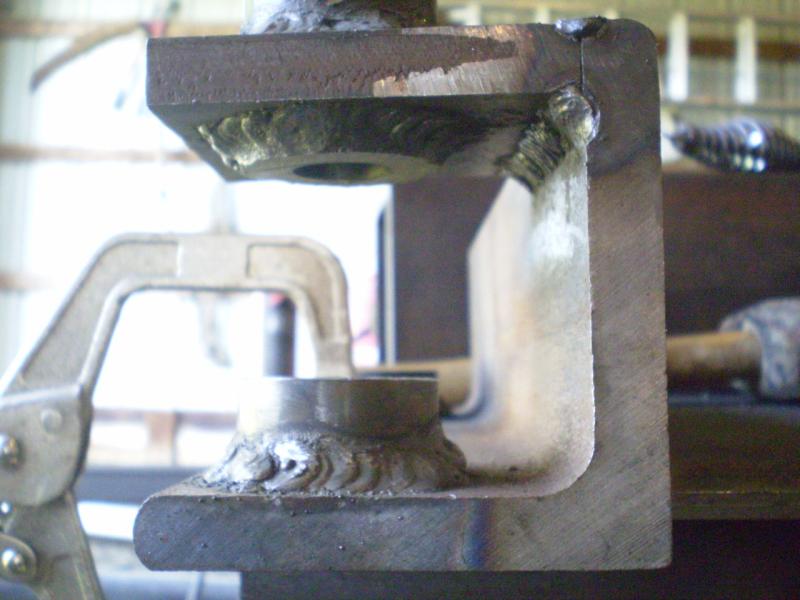
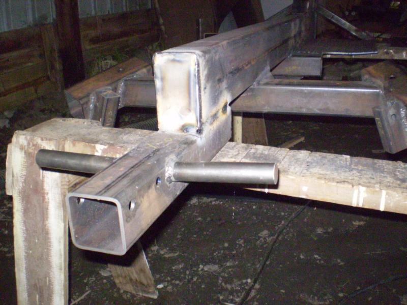
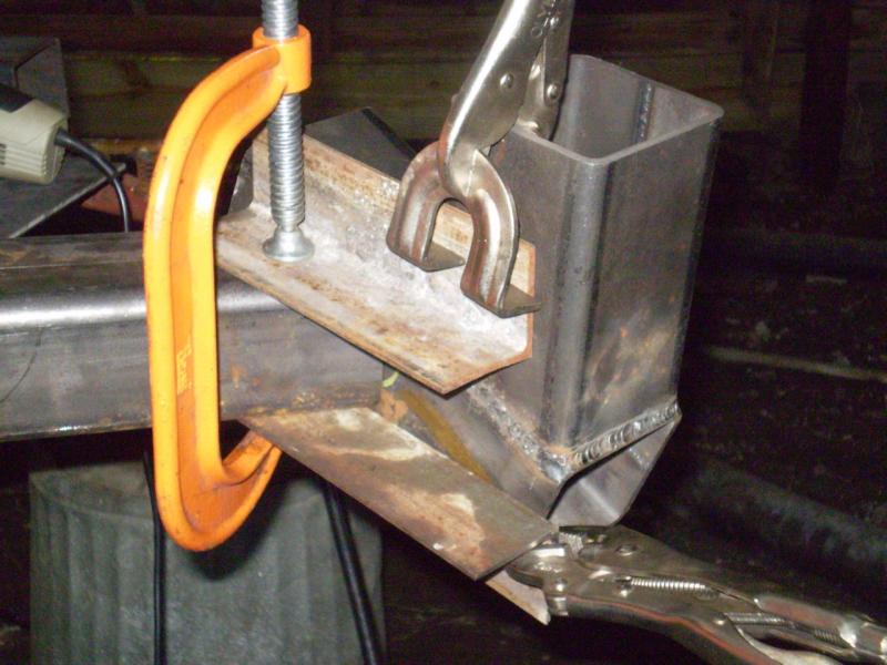 | 8 July 2007 Working on the ends of the front axles. The end-piece itself consists of the upright which will serve as the stabilizer bar storage during towing and the angled piece, which holds the stabilizer bar during digging, or the axle tube during towing.
The end-piece was easy to build. Getting it welded to the axle was tricky. The axle piece was cut at a certain angle OUT, then the end-piece had to be attached at a certain angle DOWN. The orange clamp was first used to clamp the pieces of angle, where the bottom of the angle was flush with the angle cut on the axle. Then the end-piece was placed flush against this and tilted until it reached the proper angle, then clamped in place. Once a few tack welds were added, all the clamps could come off. |
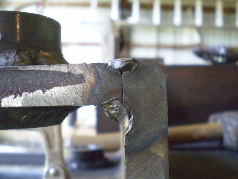
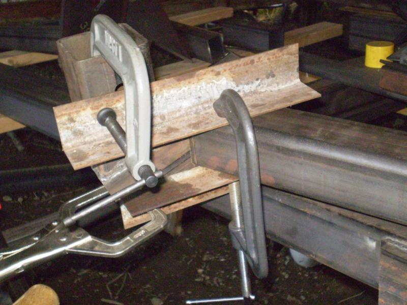 | The other end received the same treatment. |
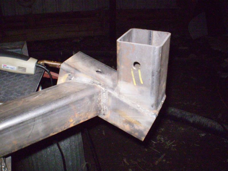 | Once welded, here is how it looked. |
 | And here is a picture showing the whole axle tube.
Note in the background that the main portion of the bucket is becoming my tool tray. Now what am I going to do when I need to build the bucket? |
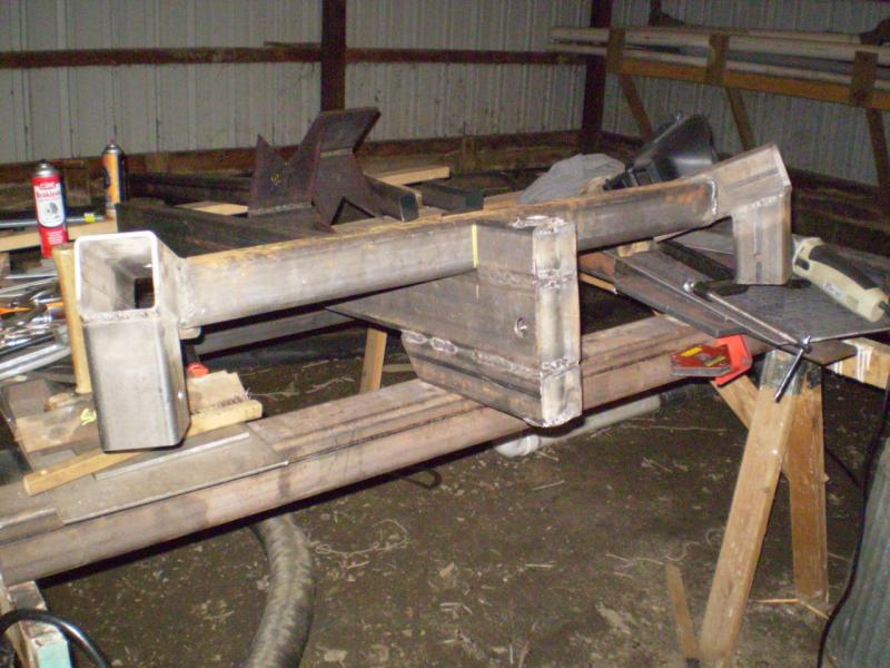 | The axle is lined up on the frame waiting for welding the next day. |
 | 15 July 2007 The main frame components have been assembled. The front axle is welded on along with some reinforcing braces and a hose loop. The rear axle has also been assembled and welded on, and the rear legs have been built.
The purpose of the rear legs is to hold the backhoe up when the wheels are in the towing position (in the front). When digging, the wheels are in the back and the rear legs are up and out of the way. |
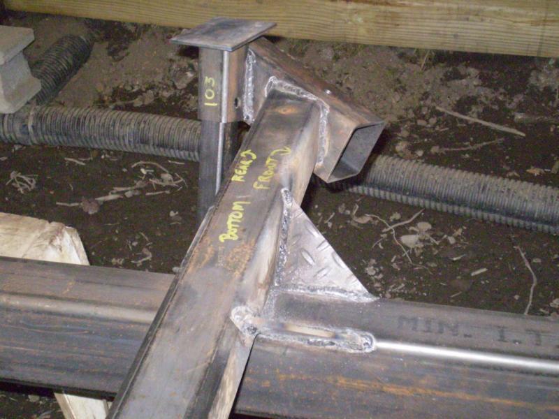 | Another view of the rear axle.
Here is another trick if you don't already do it. Freely mark up your parts to keep track of which side you are looking at and which way it goes. When you are building a component on the bench, flipping it around, etc., it's very easy to loose track of what side you are looking at, and then screw something up. The markings made it very easy to keep track of what I was looking at. |
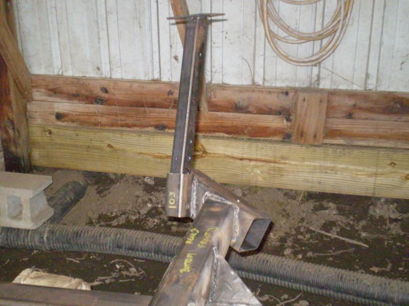 | Another shot showing one of the rear legs. |
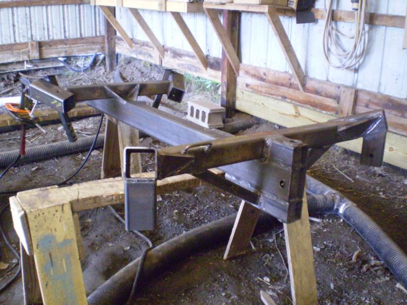
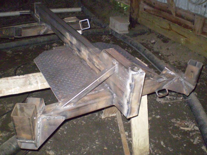
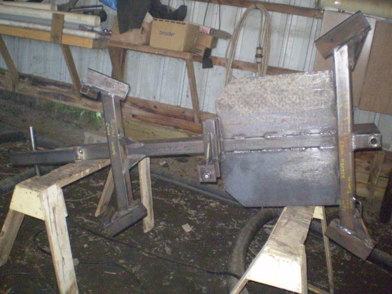 | 22 July 2007 The frame is advancing. The tread plate has been added, and the rear swing piston bracket has been built and welded in place.
This thing reminds me of some sort of giant salamander or hooded gecko lizard or something. |
 | Another view, also showing a messy shop in the background. |
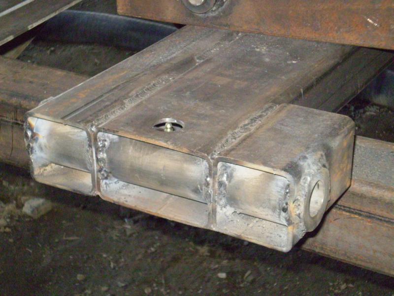
 | End caps and handles are welded on. The trailer hitch will go at this end. |
 | Another view. |
 | Front view, also with the new end cap. |
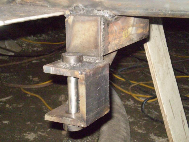 | A close-up of the rear swing piston bracket. |
 | Another angle of the rear swing piston bracket. |
|
|
|
|