INSTALLATION AND OPERATION OF POWR-TROL OIL LINE
BREAKAWAY COUPLING ON JOHN DEERE TRACTORS MODELS "50", "60", "70", "A",
"B", AND "G" WITH DETENT-TYPE POWR-TROL VALVE HOUSING (SERIAL No.
PCV67905)
Installing rear breakaway coupling and Selector Valve
Assembly.
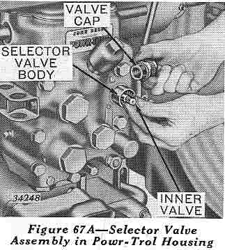
1. Rotate coupling release
lever (on right-hand side of valve housing) 1/4 turn. Remove oil line
plug from upper oil line coupling hole in Powr-Trol valve housing and
insert selector valve assembly in its place (Figure 67A).
Rotate the valve in the coupling hole and at the same time apply a
slight pressure by turning the release lever. When the detent pawl
locks in the drilled hole in the valve body, return release lever to
its locked position. CAUTION: Release lever handle must be turned to
the top to prevent damage.
2. Remove the two 3/4-inch
pipe plugs from right-hand side of Powr-Trol valve housing and screw
the two 90-degree unions into the 3/14-inch holes (Figure 67B).
3. Remove second from the
top cap screw which attaches Powr-Trol or power lift housing to rear
axle housing. Install bracket (Figure 67C) using one of the cap screws
furnished with the kit. On Models "60", "70", "A", and "G" Tractors use
the 7/16- x 1-1/2-inch cap screw. On Models "50" and "B" Tractors use
the 3/8- x 1-1/4-inch cap screw. Install the bracket with the long leg
pointing back and angling away from the tractor center line.
NOTE: On Models"60", "70", "A", "B", and "G" Tractors the bracket
may be installed on either side of the Powr-Trol housing. It is
recommended that it be installed on the right-hand side. On Model "50"
Tractors the bracket must be installed on the left-hand side of
the Powr-Trol valve housing.
Breakaway Coupling...
4. Attach the two 36-inch
flexible oil lines to the tractor half of the breakaway coupling. Place
the coupler-attaching bar on top of the bracket and insert the 7/16- x
2-3/8-inch drilled pin from the bottom. Place the spring and washer
over pin in the coupling and secure it in place by the 3/16- x 1-inch
cotter pin (Figure 68A).
5. Bring the other end of the two 36-inch flexible oil lines around
in front of the rockshaft housing and back under the battery box to the
90-degree adapter unions (Figure 68A). Attach the lines to the unions
by tightening the unions onto the hose fitting.
Instructions for Remote Cylinder Operation.
1. Remove cap from the selector valve body (Figure 67A). Turn inner
valve clockwise by hand until valve seats and replace cap. NOTE: This adjustment is in addition to the normal adjustment necessary
for remote cylinder operation as given in the Tractor Operator's
Manual.
2. Attach remote cylinder
lines to implement half of the breakaway coupling. Hose from
fixed-stop-type remote cylinder outlet marked "L," (Figure 68B) must be
attached through breakaway coupling to upper adapter union in
Powr-Trol valve housing (Figure 68A).
Hose from stop rod side of
hydraulic-stop-type remote cylinder (Figure 68C) must be attached
through breakaway coupling to lower adapter union in Powr-Trol valve
housing (Figure 68A). Connect two halves of coupling together by
exerting pressure on implement half of coupling.
Always wipe valve faces on the coupling free from dirt before the
two halves are coupled together.
NOTE: On Model "G" Tractors which have 3/4-inch remote cylinder
oil lines it will be necessary to use two JD166R adapter unions for
connecting the flexible lines to the coupling.
3. To recouple under
pressure:
Stop engine.
Move Powr-Trol lever forward to fast raise position and backward to
fast drop position to relieve oil pressure on front oil line.
Place two halves of coupling together, insert a screwdriver in the
hole slot in the coupling body and force the implement half of coupling
ahead (Figure 68D).
Instructions for Rockshaft Operation.
1. Disconnect remote
cylinder from tractor by uncoupling the breakaway. The breakaway may be
separated either by a quick pull on the hose lines which are attached
to the implement or by moving the tripping trigger toward the implement
(Figure 68E).
2. Remove cap from selector valve body (Figure 67A) and screw inner
valve out until the inside end of the knurled section lines up with the
outer end of the selector valve body. Replace cap. NOTE: This
adjustment is in addition to the normal adjustments necessary for
rockshaft operation as given in the Tractor Operator's Manual.
 1. Rotate coupling release
lever (on right-hand side of valve housing) 1/4 turn. Remove oil line
plug from upper oil line coupling hole in Powr-Trol valve housing and
insert selector valve assembly in its place (Figure 67A).
1. Rotate coupling release
lever (on right-hand side of valve housing) 1/4 turn. Remove oil line
plug from upper oil line coupling hole in Powr-Trol valve housing and
insert selector valve assembly in its place (Figure 67A).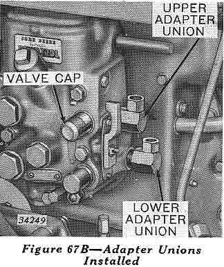 2. Remove the two 3/4-inch
pipe plugs from right-hand side of Powr-Trol valve housing and screw
the two 90-degree unions into the 3/14-inch holes (Figure 67B).
2. Remove the two 3/4-inch
pipe plugs from right-hand side of Powr-Trol valve housing and screw
the two 90-degree unions into the 3/14-inch holes (Figure 67B).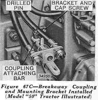 3. Remove second from the
top cap screw which attaches Powr-Trol or power lift housing to rear
axle housing. Install bracket (Figure 67C) using one of the cap screws
furnished with the kit. On Models "60", "70", "A", and "G" Tractors use
the 7/16- x 1-1/2-inch cap screw. On Models "50" and "B" Tractors use
the 3/8- x 1-1/4-inch cap screw. Install the bracket with the long leg
pointing back and angling away from the tractor center line.
3. Remove second from the
top cap screw which attaches Powr-Trol or power lift housing to rear
axle housing. Install bracket (Figure 67C) using one of the cap screws
furnished with the kit. On Models "60", "70", "A", and "G" Tractors use
the 7/16- x 1-1/2-inch cap screw. On Models "50" and "B" Tractors use
the 3/8- x 1-1/4-inch cap screw. Install the bracket with the long leg
pointing back and angling away from the tractor center line.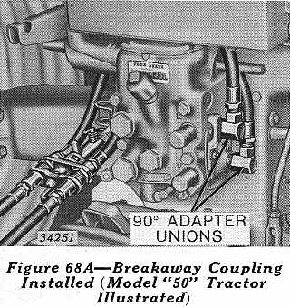 4. Attach the two 36-inch
flexible oil lines to the tractor half of the breakaway coupling. Place
the coupler-attaching bar on top of the bracket and insert the 7/16- x
2-3/8-inch drilled pin from the bottom. Place the spring and washer
over pin in the coupling and secure it in place by the 3/16- x 1-inch
cotter pin (Figure 68A).
4. Attach the two 36-inch
flexible oil lines to the tractor half of the breakaway coupling. Place
the coupler-attaching bar on top of the bracket and insert the 7/16- x
2-3/8-inch drilled pin from the bottom. Place the spring and washer
over pin in the coupling and secure it in place by the 3/16- x 1-inch
cotter pin (Figure 68A).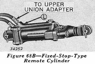 2. Attach remote cylinder
lines to implement half of the breakaway coupling. Hose from
fixed-stop-type remote cylinder outlet marked "L," (Figure 68B) must be
attached through breakaway coupling to
2. Attach remote cylinder
lines to implement half of the breakaway coupling. Hose from
fixed-stop-type remote cylinder outlet marked "L," (Figure 68B) must be
attached through breakaway coupling to 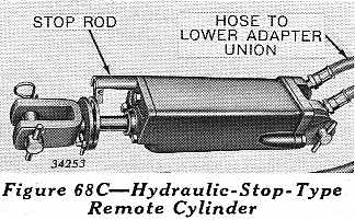 Hose from stop rod side of
hydraulic-stop-type remote cylinder (Figure 68C) must be attached
through breakaway coupling to lower adapter union in Powr-Trol valve
housing (Figure 68A). Connect two halves of coupling together by
exerting pressure on implement half of coupling.
Hose from stop rod side of
hydraulic-stop-type remote cylinder (Figure 68C) must be attached
through breakaway coupling to lower adapter union in Powr-Trol valve
housing (Figure 68A). Connect two halves of coupling together by
exerting pressure on implement half of coupling.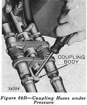 3. To recouple
 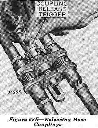 1. Disconnect remote
cylinder from tractor by uncoupling the breakaway. The breakaway may be
separated either by a quick pull on the hose lines which are attached
to the implement or by moving the tripping trigger toward the implement
(Figure 68E).
1. Disconnect remote
cylinder from tractor by uncoupling the breakaway. The breakaway may be
separated either by a quick pull on the hose lines which are attached
to the implement or by moving the tripping trigger toward the implement
(Figure 68E).