|
June, 1953 |
John Deere Service Bulletins |
No. 204 |
|
LOAD-AND-DEPTH CONTROL ANCHOR YOKE AND LOCK-OUT SCREW ADJUSTMENTS ON "40" SERIES TRACTOR |
||
|
June, 1953 |
John Deere Service Bulletins |
No. 204 |
|
LOAD-AND-DEPTH CONTROL ANCHOR YOKE AND LOCK-OUT SCREW ADJUSTMENTS ON "40" SERIES TRACTOR |
||
MODEL "40" TRICYCLE-TYPE
NOTE: Transmission rear cover assembly must be removed from the transmission case when making the following adjustments. However, it should not be necessary to change these adjustments unless parts in the rear cover assembly are to be replaced.
LOAD-AND-DEPTH CONTROL ANCHOR YOKE ADJUSTMENT
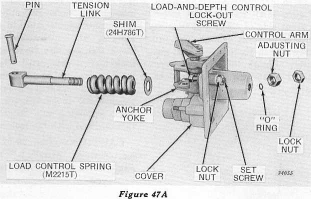
If rear cover has been disassembled, refer to Figure 47A, showing
relative position of parts for assembling.
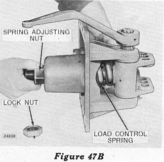 Install special load spring
adjusting nut with counter-bore in nut toward spring. Grasp spring and
tighten adjusting nut until end-play or free movement of spring is just
eliminated (Figure 47B).
Install special load spring
adjusting nut with counter-bore in nut toward spring. Grasp spring and
tighten adjusting nut until end-play or free movement of spring is just
eliminated (Figure 47B).
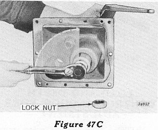 Then tighten the adjusting
nut an additional 1/4 turn (Figure 47C). Secure adjusting nut in this
position with lock nut.
Then tighten the adjusting
nut an additional 1/4 turn (Figure 47C). Secure adjusting nut in this
position with lock nut.
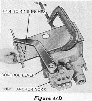 Check the above adjustment
in the following manner: Clamp a steel plate measuring about 6 inches
wide and 18 inches long to the transmission rear cover as shown in
Figure 47D. The measurement from the edge of the mounting surface on
the cover assembly to the center of the hole in the control lever as
shown in Figure 47D, should be 4-1/4 to 4-5/8 inches. If the dimension
is less than 4-1/4, add a shim under the load control spring. If the
dimension is more than 4-5/8 inches, remove the shim from under load
control spring. Each time a shim is added or subtracted, follow the
adjustment procedure very carefully. Always check adjustment after
adding or removing a shim.
Check the above adjustment
in the following manner: Clamp a steel plate measuring about 6 inches
wide and 18 inches long to the transmission rear cover as shown in
Figure 47D. The measurement from the edge of the mounting surface on
the cover assembly to the center of the hole in the control lever as
shown in Figure 47D, should be 4-1/4 to 4-5/8 inches. If the dimension
is less than 4-1/4, add a shim under the load control spring. If the
dimension is more than 4-5/8 inches, remove the shim from under load
control spring. Each time a shim is added or subtracted, follow the
adjustment procedure very carefully. Always check adjustment after
adding or removing a shim.
ADJUSTMENT OF STOP FOR LOAD-AND-DEPTH CONTROL LOCK-OUT SCREW
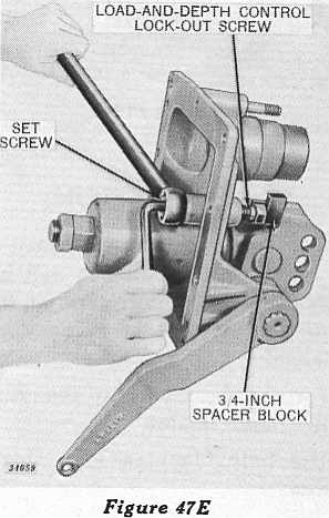 After the 4-1/4- to
4-5/8-inch dimension has been established, place a 3/4-inch steel
spacer block across the flat on the lock-out screw head and back screw
out until block just contacts the anchor yoke stop lug (Figure 47E).
Block must be held flat on lockout screw head. Next, turn set
screw into cover until it just contacts the lock-out screw. Lock set
screw securely in this position with special lock nut (Figure 47E).
After the 4-1/4- to
4-5/8-inch dimension has been established, place a 3/4-inch steel
spacer block across the flat on the lock-out screw head and back screw
out until block just contacts the anchor yoke stop lug (Figure 47E).
Block must be held flat on lockout screw head. Next, turn set
screw into cover until it just contacts the lock-out screw. Lock set
screw securely in this position with special lock nut (Figure 47E).
MODEL "40" STANDARD
ADJUSTMENT OF STOP FOR LOAD-AND-DEPTH CONTROL LOCK-OUT SCREW
NOTE: The transmission rear cover assembly must be removed from the transmission case when making this adjustment. However, it should not be necessary to change the adjustment unless a new cover, lock-out screw, or set screw are to be installed.
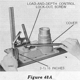 Loosen lock nut and remove
set-screw from front or inside of transmission rear cover and place
cover on a flat surface. Install Load-and Depth Control lock-out screw
in rear or outside of cover and adjust lock-out screw in cover until
2-15/16-inch dimension is obtained (Figure 48A).
Loosen lock nut and remove
set-screw from front or inside of transmission rear cover and place
cover on a flat surface. Install Load-and Depth Control lock-out screw
in rear or outside of cover and adjust lock-out screw in cover until
2-15/16-inch dimension is obtained (Figure 48A).
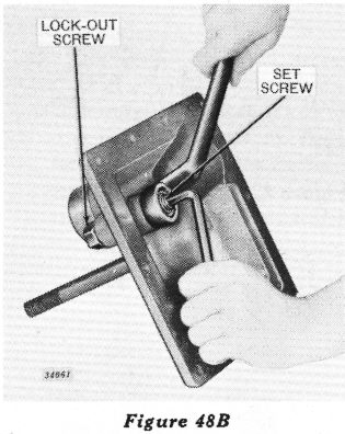 Reinstall set-screw in front
side of cover and turn in until it bottoms against lock-out screw. Then
tighten lock nut securely (Figure 48B) making sure that 2-15/16-inch
dimension does not change.
Reinstall set-screw in front
side of cover and turn in until it bottoms against lock-out screw. Then
tighten lock nut securely (Figure 48B) making sure that 2-15/16-inch
dimension does not change.
LOAD-AND-DEPTH CONTROL ANCHOR YOKE ADJUSTMENT
NOTE: The transmission rear cover and anchor yoke assemblies must be installed on the tractor in their relative positions before this adjustment can be made.
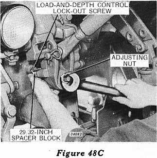 Turn the Load-and-Depth
Control lock-out screw into the transmission rear cover assembly until
it bottoms against stop in cover. Hold a 29/32-inch steel spacer block
flat on the head of the lock-out screw and tighten load control
spring adjusting nut until anchor yoke stop lug just touches the block
(Figure 48C). Lock adjusting nut securely in this position with the
lock nut.
Turn the Load-and-Depth
Control lock-out screw into the transmission rear cover assembly until
it bottoms against stop in cover. Hold a 29/32-inch steel spacer block
flat on the head of the lock-out screw and tighten load control
spring adjusting nut until anchor yoke stop lug just touches the block
(Figure 48C). Lock adjusting nut securely in this position with the
lock nut.
CAUTION: The 29/32-inch adjustment must be re-set each time the
anchor yoke is removed.