|
September, 1954 |
John Deere Service Bulletins |
No. 219 |
|
LOAD-AND-DEPTH CONTROL ANCHOR YOKE AND LOCK-OUT
SCREW ADJUSTMENTS |
||
|
September, 1954 |
John Deere Service Bulletins |
No. 219 |
|
LOAD-AND-DEPTH CONTROL ANCHOR YOKE AND LOCK-OUT
SCREW ADJUSTMENTS |
||
NOTE: To facilitate removal of the spring housing assembly from the rockshaft housing, it is recommended that the control arm be moved from the anchor yoke.
Load-and-Depth Control Anchor Yoke Adjustment
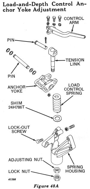 If the anchor yoke and
spring housing assembly has been completely disassembled, refer to
Figure 48A for relative location of parts for assembling. Install
special load spring adjusting nut with counterbore in nut toward
spring.
If the anchor yoke and
spring housing assembly has been completely disassembled, refer to
Figure 48A for relative location of parts for assembling. Install
special load spring adjusting nut with counterbore in nut toward
spring.
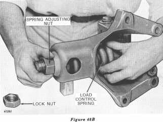 Grasp spring and tighten
adjusting nut until end play or free movement of spring is just
eliminated (Figure 48B).
Grasp spring and tighten
adjusting nut until end play or free movement of spring is just
eliminated (Figure 48B).
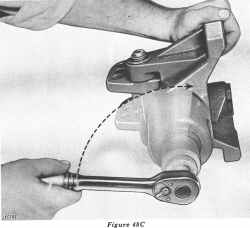 Then tighten the adjusting
nut 1/4 turn (Figure 48C). Secure adjusting nut in this position with
lock nut.
Then tighten the adjusting
nut 1/4 turn (Figure 48C). Secure adjusting nut in this position with
lock nut.
Check the above adjustment in the following manner:
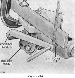 Clamp a steel bar to the
spring housing mounting bosses as shown in Figure 49A. The measurement
from the face of the mounting bosses to the center of the hole in the
control arm should be 3/8- to 7/8-inch (Figure 49A). If the dimension
is less than 3/8-inch, remove a shim from under the load control
spring. If the dimension is more than 7/8-inch, add a shim under the
load control spring. Each time a shim is added or removed, follow the
adjustment procedure very carefully. Always check adjustment after
adding or removing a shim.
Clamp a steel bar to the
spring housing mounting bosses as shown in Figure 49A. The measurement
from the face of the mounting bosses to the center of the hole in the
control arm should be 3/8- to 7/8-inch (Figure 49A). If the dimension
is less than 3/8-inch, remove a shim from under the load control
spring. If the dimension is more than 7/8-inch, add a shim under the
load control spring. Each time a shim is added or removed, follow the
adjustment procedure very carefully. Always check adjustment after
adding or removing a shim.
Adjustment of Stop for Load-and-Depth Control Lock-Out Screw
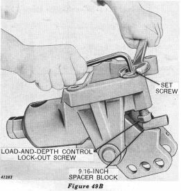 After the 3/8- to 7/8-inch
dimension has been established, place a 9/16-inch steel spacer block
across the flat on the lockout screw head and back screw out until
block just contacts the anchor yoke stop lug (Figure 49B). Spacer
block must be held flat on lock-out screw head. Next, turn set
screw into cover until it just contacts the lock-out screw. Lock set
screw securely in this position with lock nut (Figure 49B).
After the 3/8- to 7/8-inch
dimension has been established, place a 9/16-inch steel spacer block
across the flat on the lockout screw head and back screw out until
block just contacts the anchor yoke stop lug (Figure 49B). Spacer
block must be held flat on lock-out screw head. Next, turn set
screw into cover until it just contacts the lock-out screw. Lock set
screw securely in this position with lock nut (Figure 49B).
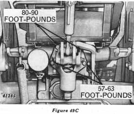 CAUTION: When
reinstalling the spring housing assembly on the rockshaft housing, it
is very important that the attaching cap screws be tightened to the
following torque values:
CAUTION: When
reinstalling the spring housing assembly on the rockshaft housing, it
is very important that the attaching cap screws be tightened to the
following torque values:
Tighten 1/2-inch cap screws to 57 to 63 ft.-lbs.
Tighten 9/16-inch cap screws to 80 to 90 ft.-lbs.
Refer to Figure 49C for location of these cap screws.
Lift Arm Maximum Raise Adjustments
After the spring housing assembly has been installed on the tractor and the control arm and ball joint linkage have been connected, check the maximum raise of the lift arms in the following manner:
Start engine and slowly pull Touch-o-matic control lever to its extreme rear position. Stop engine and check free travel of lift arms by raising them until stop in housing is reached. The free travel should be approximately 1 to 1-1/2 inches when measured at the hole in the outer end of the lift arms. The amount of free travel can be changed by altering the length of the ball joint linkage between the control arm and the equalizing lever in the Load-and-Depth Control system.