ESTABLISHING GAUGE MARKS AND ALIGNING TRACK
CARRIERS
John Deere Models "MC" and "40" Crawler Tractors
The following instructions are provided for use in establishing
gauge marks on field replacement crossbar members, and for
reestablishing gauge marks which have been obliterated on crossbars on
crawler tractors in the field.
LOCATION OF GAUGE MARKS ON CROSSBAR MEMBERS
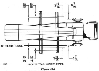
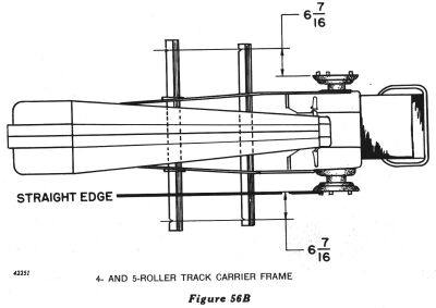
Figures 56A and 56B are schematic drawings of Model "MC" and Model
"40" Crawler Tractors, respectively, showing the relationship between
the gauge marks on the crossbar members and the face of the sprocket
driving hub.
To establish gauge marks on a crossbar member, proceed as
follows:
Disconnect tracks.
Remove old crossbar member from tractor and install new one. (Do not
clamp crossbar member to track carrier frame assemblies at this
time.)
Remove sprocket from driving hub.
Clamp a straight-edge across the face of the sprocket drive hub,
allowing it to extend forward over both front and rear crossbar members
(Figures 56A and 56B).
Measure 6-7/16 inches out from the face of sprocket drive hub and
make chisel marks on the forward corner of both the front and rear
crossbar members (Figures 56A and 56B).
If the tractor is of the 3-roller type, refer to Figure 56A and make
three more gauge marks on each crossbar member.
If the tractor is of the 4- or 5-roller type, one gauge mark on each
crossbar is all that is necessary.
Repeat steps "3" through "7" on other side of tractor.
ALIGNMENT OF TRACK CARRIER FRAMES ON CROSSBAR MEMBERS
Three-Roller Type Track Carrier Frames.
Slide track carrier frame assembly inward or outward to the
approximate tread setting and install drive sprocket. NOTE: The four gauge marks, reading from outer end of crossbar
members toward center of tractor, are 46, 44, 38, and 36
inches.
Make certain the proper mark is used on both front and rear
crossbars and that the marks are lined up with the inside edge of the
outer track carrier frame plate.
Tighten the eight nuts, which hold the track carrier frames to the
cross-member bars, evenly and securely.
Repeat steps "1" through "3" on other side of tractor.
Four- and Five-Roller Type Track Carrier Frames.
Slide track carrier frame assembly inward or outward to the
approximate tread setting and install drive sprocket. NOTE: Tread settings of 46, 44, 38, and 36 inches are possible,
depending upon drive sprocket.
Shift rear of track carrier frame assembly so that sprocket rim is
centered in groove between rear roller flanges, and clearance is
equalized to compensate for sprocket runout.
Measure distance from gauge mark to track frame clamp screw.
Position front of track carrier frame assembly so that front track
frame clamp screws are the same distance inboard from gauge mark as the
rear track frame clamp screws.
Tighten the eight track frame clamp attaching cap screws to proper
torque specifications. (See article in column 3 of this page.)
Repeat steps "1" through "4" on other side of tractor.
TRACK TENSION
Connect tracks and adjust track tension bolts evenly until the
following track sag dimensions are obtained: